Component recovery and electronics repair. How does the Martin station work in the Comarch IoT Plant?

Due to the lack of market availability of components and BGAs, customers are seeking recovery services for hard-to-recover and expensive components. This solution makes it possible to assemble new electronic packages in a faster and more cost-effective way and reduces the waiting time for the final product. At the Comarch IoT Plant, we use a Martin Expert 10.6HV soldering station for this purpose which allows the efficient replacement of faulty components in electronic packages. What does this look like in practice?
Electronics repair process using Martin stations
Bottom heater functions
An important part of repairing electronic components is the correct temperature management. The Martin station is equipped with a hybrid bottom heating system, since local heating from above would lead to undesirable stresses that damage components and cause permanent deformation of PCB layouts. To avoid this, the entire printed circuit board is heated to a temperature in the range of 100-170°C. It is important that the heat is distributed thoroughly over the entire surface of the circuit. Martin heaters are designed to:
- distribute the heat evenly over the boards,
- avoid spot discolouration of the PCB,
- avoid deformation,
- accurately stabilise and control the temperature throughout the heating process.
– “Adjusting the right temperature is a key factor here. If particularly sensitive components, such as plastic sockets, displays or capacitors, are present on the PCBs, the temperature must be reduced accordingly, as the risk margin for damaging them remains relatively low” – explains Marcin Dziadzio, Electronics Assembler at Comarch IoT Plant.
When heaters are used in the repair of electronic packages, simple, uncomplicated operation is equally important. Units to be repaired or modified should be suitable for processing without the need to attach additional thermocouple devices. To this end, the heaters can operate in one of two modes:
- Power control. In this mode, the heater operates according to pre-programmed or pre-learned heating profiles. It therefore does not require temperature sensors and is the default mode for profile operation – it functions as 'Open Loop Operation’ in the EASY SOLDER software.
- Temperature-controlled operation. In this mode, a thermocouple module attached to the PCB measures the temperature continuously. The software compares the actual temperature with that specified as the required temperature and compensates for the difference. The result is a feedback loop that ensures a constant board temperature. This mode functions as ‘Closed loop’ in the EASY SOLDER software.

Top heater functions
The top heating in Martin Rework systems is provided by a highly efficient, compact hot air source. An electrically powered top heater heats the ambient air. To adjust the heat flow to a specific point, it can be set to: 4, 5, 6, 8, 10, 13, 16, 20, 25, 30 or 35 l/min.
– “The hot air provides optimum heating or cooling conditions for electronic components. In this way, excellent temperature control can be achieved. Appropriately sized nozzles allow the hot air to be directed with great accuracy at the required soldering joints of individual components, while protecting, where possible, their sensitive parts” – says Marcin Dziadzio.
For surface mount components (SMT, Surface Mount Technology), datasheets are available which give the recommended soldering temperatures. The EASY SOLDER control software makes it possible to precisely determine temperature profiles that are within specified limits.
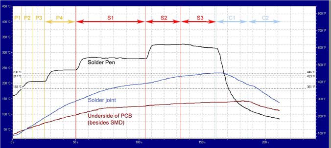
Setting the temperature profile
When setting the temperature profile of the PCB, attention should be paid to the maximum allowable temperatures of the heat-sensitive components mentioned above, namely the sockets, capacitors and displays. Sometimes individual components may require shielding, i.e. the use appropriately made shields. Thermocouple sensors are attached with Kapton tape as close as possible to the component to be repaired on the electronic package. As the tips of the thermocouple are electrically conductive, the position is selected so as to avoid coming into contact with any conductive surface, which could cause a measurement error.
Automated Vision Placement (AVP) – positioning process
When working on a PCB, Martin Rework Systems offers a unique technique for placing the SMD (Surface Mount Device) components with minimal operator interaction with the components during the positioning process. The operator performs positioning solely on the computer screen. The alignment is done very close to the PCB and with full control via a CCD camera. How does it work?
– “The AVP process involves accurate positioning, the target placement of components on the PCB with the help of a camera. First, the operator indicates the outline of the location on the board and, in the next step, specifies the outline of the component to be placed. All operations are done with a computer mouse. The alignment and positioning process is then already done automatically by the software. At the end, the system shows a view of the finished position and allows the operator to verify and approve it” – adds Marcin Dziadzio.

7 key steps in the BGA unit replacement
- Fixing the electronic package at the repair station and securing sensitive components.
- Creation of a new temperature profile by using bottom and top heating with thermocouple sensors connected.
- End of heating – the de-soldered circuit is lifted by a pneumatic gripper.
- Cleaning the tin residue on the PCB by applying flux, heating locally with hot air and sucking the liquid tin into a pneumatic nozzle.
- Positioning of the new BGA unit in the AVP function.
- Soldering of the new circuit with the temperature profile set in step 2.
- Final inspection.
Reballing – renewing soldered connections
A related process to, but not performed with, the Martin station for repairing electronic systems is reballing, a procedure for renewing the connection. It is used when the customer or our production team plan to reuse a particular BGA component, e.g. in an alternative design, when cost and time are of the essence. In this case, de-soldering the component requires the connection to be renewed. The refurbished system is then suitable for installation already at the Martin station.
To perform the reballing correctly, you need to:
- Fix the circuit in the holder, apply flux and clean up any residual tin (items such as copper braid and a soldering iron station with a soldering iron tip are useful here).
- Clean the system of flux residues.
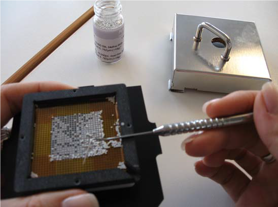
- Apply new flux and mount the chip in the appropriate BGA ball positioning templates (templates are ordered individually for each chip).
- Position the BGA balls on the template by spreading into the appropriate holes and then scraping off the excess into a container.
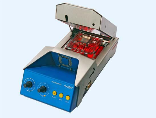
- Fixing the holder with the chip in the MiniOven and heating (the temperature profile is matched to the chip to be treated).
- Quality control of the balls after heating.


The BGA reballing allows it to be reused in electronic packages.
Comarch IoT Plant – much more than electronics recovery and repair
– “Due to global manufacturing and storage shortages, the recovery and repair of electronic components is becoming increasingly popular. This is because they contribute to increased resource efficiency, financial savings, reduction in electronic waste and reduction in harmful environmental impacts. As part of the Comarch IoT Plant, our state-of-the-art laboratory and production facility, we offer customers, among other things, electronics recycling which allows us to successfully respond to current market challenges” – adds Marcin Dziadzio.
The Comarch IoT Plant offers not only high-quality services for the recovery and repair of components and BGAs, but also for rapid prototyping, electronic device assembly (EMS) and testing. More on the Comarch IoT Plant website.